Evolving ESPway, the self-balancing robot
Remember ESPway, the self-balancing robot I introduced a year ago? I’ve been totally drawn by the project, and during the past year it has been vastly improved in many aspects. This post goes through these and the associated learning process. There’s also some cool maze solver stuff implemented!
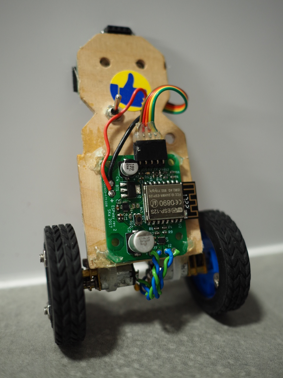
For those of you not familiar with the project, it is a WiFi controllable self-balancing robot designed to be small, elegant and cheap to build. These goals have been achieved by using the popular ESP8266 microcontroller as the sole processor. I’m still not aware of any other robot that is implemented in a similar manner, i.e. without a slave processor doing some of the tasks. You can find the code, schematics, PCB and associated documents on GitHub.
Custom board, component changes
The first iteration of the robot was built out of breakout boards that one can order for eBay and other sources. However, assembling multiple copies of such a device gets old quite fast, mainly due to the excessive amount of wiring that has to be done. Also the design has turned out to be a bit fragile.
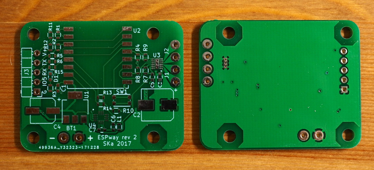
I’d been wanting to learn surface mount design and soldering for a long time. Hence the natural next step was to design a custom printed circuit board for the robot. KiCad was surprisingly easy to learn, and in little time I was routing my first PCB.
For this design I wanted to get rid of any standalone breakout boards - the ESP-12S module not counting, naturally. However, that meant that the IMU had to change: I realized that MPU6050 is quite highly priced at small quantities. I swapped it out for STmicro’s LSM6DS3 which is similar, if not a little better, for all practical purposes of this project, being priced at about half the price of MPU6050 in small quantities. As a bonus, it clocks out gyro and accelerometer samples at a nice 1.66 kHz rate (vs 1 kHz for MPU6050). Overall, the switch was pretty easy and mostly a matter of finding correspoding registers in the chip’s datasheet.
Another change from the earlier design was swapping out the L293D motor driver for the smaller DRV8835. L293D, being a classic in hobbyiest robot designs, is quite old technology. The H-bridges driving the motors are made of bipolar transistors, giving a voltage drop of a couple of volts per motor. I realized I was turning battery power into heat instead of driving the motors harder! Therefore I opted for the MOSFET based, otherwise similar driver DRV8835. It really made a difference: the robot gained a lot of speed and stability due to the change.
Otherwise, I realized the ESP8266 module had still one unused GPIO pin (not counting the GPIO16 which is a bit special) so I decided to expose it on a pin header, along with the RX and TX pins for programming, of course. It was a good decision, as the pin found some good use quite fast - read on to find out!
The PCB and circuit design has turned out pretty robust so far, despite me giving it quite a beating.
Real-time goodness
One problem I was having with the earlier Arduino/non-OS SDK based design was jitter — during WiFi or web server activity, the robot’s balance would often jitter as the network code took all the CPU time for long periods, not allowing the balancing algorithm to run. That is due to the event-based, OS-less architecture of the aforementioned frameworks. There is no way to organize tasks by priority.
The natural solution to this problem is a real-time operating system. The key feature we are looking for here is the ability to schedule the IMU data processing at a higher priority than any other task, including the network stack. Given this kind of a configuration, when an interrupt from the IMU arrives, indicating the availability of new data, it is ensured that this data is always processed first, before doing anything else.
There are a couple of options for a RTOS running on ESP8266:
- ESP8266 RTOS SDK provided by the manufacturer Espressif, based on FreeRTOS
- Simba by Erik Moqvist, custom scheduler
- esp-open-rtos, based on FreeRTOS
The SDKs provided by Espressif have been less than stellar in terms of usability and support, from my experience (although it seems to have changed with esp-idf for ESP32!), and therefore I did not consider the RTOS SDK as a viable option.
Simba seems pretty nice, being developed by an independent developer and supporting a wealth of different platforms. The engineering and architecture looks pretty sturdy, and I intend to experiment with it in the future.
For this project, however, I chose esp-open-rtos for a couple of reasons. Firstly, it has a sane set of APIs for accessing the ESP8266 peripherals, much unlike Espressif’s macro-heavy “libraries” which look like they were never meant to face the general public.
esp-open-rtos has also a couple of active contributors, some investing large amounts of time in reverse-engineering parts of the original SDK, driving the environment towards the upstream versions of the software components used, e.g. lwIP and FreeRTOS, which are nowadays consistently kept up to date within the framework. This helps us avoid some of the long-standing bugs in the old version of lwIP used in the official SDKs. Being closer to upstream code also gives better stability and new features.
Note: despite my slight ranting about Espressif’s SDK work, I’m pretty impressed with their investment in the ESP32 support! I guess they’ve learned their lesson.
Algorithm and driver improvements
In order to facilitate the higher data rate offered by the new IMU, I wanted optimize some of the algorithms in the tightest loop. Firstly, the I2C driver in esp-open-rtos wasn’t giving out the clock rates it promised — even 160 MHz CPU clock, it would only produce approximately 500 kHz on the clock line. It turned out there was a problem in the busy-waiting delay loop which caused loss of performance in the software I2C driver. I did some fixes and optimizations in the driver and sent these to upstream. As a result, I could produce a 1300 kHz SCL signal at maximum (although at that point it is a bit unstable, given that it’s generated by software). The sensor seems to accept this, though, and I’m happy that I could minimize the time taken by data readout.
Secondly, the sensor fusion algorithm combining the gyro and accelerometer signals to yield the orientation is pretty heavy. Previously I was using the Madgwick algorithm that gives a full quaternion (three degrees of freedom) as a result. Turns out, however, that I don’t need the yaw angle anywhere in the firmware. The reading would not be reliable anyway since none of the sensors can give an absolute reference for that angle.
I opted to use the Mahony filter instead, and chose to only estimate the gravity vector (two degrees of freedom) instead of a full quaternion. Gravity vector is enough to get the pitch and roll angles which are necessary in this robot. The filter I’m using is nicely described here. The algorithm is simpler than the previous one, freeing up some CPU time for other tasks (e.g. the WebSocket communication with clients).
The motor drive scheme was also changed. Previously I was using a software PWM library that did quite well in this application. However, the licensing turned out to be incompatible (my code being LGPL, the library GPL), preventing me from distributing binaries of the firmware (something I’d like to do in the future). Therefore I decided to roll my own and try something new. I’d recently learnt about delta-sigma modulation which is essentially a pulse density modulation method (as opposed to pulse width modulation where a constant frequency is maintained). It is light on the CPU while retaining good resolution. Turns out it works pretty well for controlling DC motors, not to forget that it could be easily adaptible for controlling stepper motors in the future.
Maze solver
Lastly, I would like to show a nice little thing that could be quite easily implemented thanks to the evolutionary steps described above.
There was a gathering of Finnish hackerspaces last weekend. Traditionally there has been a robot competition where one must go around a simple track as fast as possible. The competition is quite playful, focusing on the entertainment value of the robots. Anyway, I decided to give a try at making ESPway solve the track.
Given that there is an extra unused GPIO pin exposed on the pin header, I decided I would hook an ultrasonic sensor there, pointing to the side of the robot and implement a simple wall follower tracing a wall on the right in case one is found. Additionally, I thought an ultrasonic sensor pointing in the front direction would be useful — it would be used to detect if there is a wall ahead. It turns out the TX pin that was also exposed on the pin header, is unused at runtime and could be repurposed for another ultrasonic sensor.
The sensors I used were some of the cheapest HC-SR04 ultrasonic sensors one can get on eBay. Note that I’m sharing the same GPIO pin for trigger and echo pins to save some pins. Despite some nasty behaviour of these sensors reported on the Internet by other users, these work surprisingly well at distances of several tens of centimeters, just what I need for the track. However, to eliminate some potential outliers, a running median buffer of five samples was implemented.
The algorithm itself is pretty simple:
- If there is a wall nearby in the front, turn left.
- If there is a wall on the right, follow it.
- If no wall is detected, go forward, turning slightly right.
Items 1 and 2 are implemented using a proportional-derivative control scheme. The algorithm is not optimal, and it could be easily fooled to turn to the wrong direction and go back instead of progressing in the maze. However, in practice it fared pretty well in the competition. See the video on YouTube.
Software-wise, the wall follower functionality was nice and easy to implement. That’s mainly thanks to the underlying real-time operating system. The wall follower could simply be implemented as a standalone task or routine which just reads the ultrasonic sensors and sends steering commands to the motion control algorithm.
Goings on
The next increments for ESPway are a 3D printable body (I’ve got some ideas already) and an overhaul of the browser GUI. I’d also like to improve the project’s documentation to make it more easy for others to build their own ESPway. The first step is to organize the code and design files better. Therefore I’ve created an organization for ESPway on GitHub where all the relevant repos are located.
In the future, I would also like to build a larger ESPway, powered by stepper motors. As the algorithms and control are quite refined, the performance is now mainly up to the motors and backlash in the gearboxes. Using direct drive with stepper motors should vastly improve the situation!
